The moment a toe clamp comes down on a 2 mm aluminum cover plate, the flatness battle is already lost. A thin wall, a wide web, or a large face sitting on a skinny cross-section cannot fight back against a point load — it bends before the cutter ever touches it, and it springs back the instant the clamp releases. Vacuum workholding exists to solve exactly this class of part. Instead of squeezing the part at a handful of contact points, it holds the entire underside with a pressure that spreads itself evenly across every square millimeter, so there is no single point of load to bow the metal. But vacuum is not a magic wand. It is a holding-force calculation, and if the math or the fixture is wrong, the part lifts mid-cut and the tool ploughs through it. This guide covers when vacuum is the right call, how much grip you actually get, and the cutting rules that keep a thin part flat from the first pass to the last.
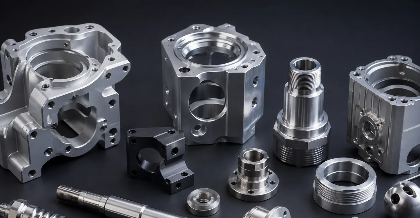
Why clamps are the wrong tool for a thin part
A mechanical clamp works by applying a concentrated load at a contact point, and everything a thin part does wrong traces back to that concentration. A vise jaw or a toe clamp pushes on a small patch of surface, and the part — because it is thin — deflects elastically under that load before the tool ever engages. The deflection shows up in three places. First, the part is bent during the cut, so the cutter machines a flat profile into a curved surface; when the clamp releases, the part straightens and the machined face comes out bowed. Second, the clamp force itself distorts the part, so the geometry you measure while clamped is not the geometry you ship. Third, any residual stress left from the clamping is released unevenly, which is why a thin plate that measured flat on the machine can spring into a potato-chip the moment it is unbolted.
The fix is not to clamp harder — that only makes the bow worse. The fix is to stop applying point loads altogether. This is the core argument for vacuum: it replaces a few concentrated forces with a single, distributed pressure that acts over the whole contact face. A part held by vacuum is not squeezed at all; it is pushed uniformly against a flat reference surface, so it cannot be distorted by its own workholding. For anything with a wall under roughly 3 mm, a wide unsupported span, or a tight flatness callout, vacuum stops being a convenience and becomes the only workholding method that does not fight the tolerance.
What a vacuum fixture actually does — and where it stops working
Vacuum does not pull a part down. It is the atmosphere that pushes, and the fixture simply removes the air from underneath so there is nothing pushing back up. Seal a part against a chamber, pump the air out of that chamber, and the weight of the atmosphere above the part presses it onto the fixture face at roughly 100 kPa — about 1 kilogram-force on every square centimeter, minus whatever is left in the chamber. Because that pressure acts everywhere at once, the load is uniform: no stress risers, no localized deflection, no springback when the part comes off. A part with a genuinely flat, well-sealed back face will sit down hard and stay put.
That last sentence hides the limits. Vacuum only holds against forces that try to lift the part off the fixture; it is much weaker against sideways forces, which is why a vacuum fixture needs locator pins, rails, or a surrounding nest to take the shear load of a cut. It also fails quietly. A single through-hole, slot, or a back face with a bad surface finish leaks air, and the holding force drops faster than the operator notices. A porous or highly perforated part may never pull down at all. And a part with a small footprint has little area for the pressure to act on, so it develops little grip no matter how hard the pump pulls. Vacuum is the best tool in the box for thin, flat, reasonably sealed parts — and the wrong tool for everything else.
How much holding force do you really get: the math
The holding force of a vacuum fixture is straightforward to estimate, and worth doing before you commit a part to it. The grip is the pressure differential times the effective sealed area. The differential is the atmosphere (about 100 kPa) minus the absolute pressure left in the chamber, so a fixture pulling 80 kPa below atmosphere leaves a net push of roughly 80 kPa. That is 8 newtons on every square centimeter, or about 0.8 kilogram-force. The effective area is not the whole part — it is the area over which the pressure actually acts, reduced by any grooves, gasket land, or leaked-through feature. Multiply the two and you get a number you can compare directly against the cutting force your toolpath is trying to generate.
The table below is the quick reference version. A 10 cm by 10 cm plate is a useful mental benchmark: at a modest 60 kPa differential it holds around 600 N, and at a good 80 kPa it approaches 800 N — enough to resist a light milling pass, but not a full-depth slotting cut that is trying to rip the part sideways and up. The rule of thumb is to keep your cutting force to a fraction of the holding force, because the number on paper assumes a perfect seal, and a perfect seal is the first thing a chip or a coolant film will ruin.
| Differential pressure | Force per cm² | Grip on a 10×10 cm plate | Typical use |
|---|---|---|---|
| 40 kPa | 4.0 N | ~400 N | Finish-only cuts, engraving, locator assist |
| 60 kPa | 6.0 N | ~600 N | Light covers, panels, shallow profiles |
| 80 kPa | 8.0 N | ~800 N | Typical milling of thin plates and webs |
| 95 kPa | 9.5 N | ~950 N | Near-full vacuum, heaviest viable cuts |
Fixture design: grooves, gaskets, and locators
The difference between a vacuum fixture that holds and one that leaks is almost always in the sealing, not the pump. The chamber is usually a network of shallow grooves milled into the fixture face, sealed around the edge by a gasket or O-ring so the part itself becomes the lid. The groove pattern matters less than people expect; what matters is that the sealed area is large, that the gasket sits proud enough to seal but not so high that it lifts the part off the flat reference face, and that the reference face itself is flat and clean, because any gap is a leak. For a part with through-features, the features have to be either plugged, zoned off behind separate gasket islands, or accepted as lost area in the force calculation.
Side loads are the other half of the design. A vacuum fixture resists lift well and shear poorly, so it needs something mechanical to take the sideways component of every cut — a couple of locating pins, a shallow nest, or an edge rail that the part butts against. Without them, a climb-milling pass that should be harmless can walk the part across the fixture face until it breaks the seal. The choice of fixture style then follows the part shape, and the table below lays out the common options.
| Fixture style | How it seals | Best for | Watch out for |
|---|---|---|---|
| Grooved plate | Gasket or O-ring seals the part edge | Flat covers, panels, plates | Through-holes leak; needs a good back finish |
| Porous / sintered chuck | Air drawn through the whole porous face | Very thin, delicate, or perforated parts | Lower grip per area; face wears over time |
| Pocket / nest plate | Part sits in a machined pocket, vacuum in the cavity | Parts with a lip, rim, or non-flat back | Needs a matching pocket per part family |
| Zoned inserts | Sealed pads under specific regions | Large thin castings, heat sinks, webs | Requires zone planning and more plumbing |
Cutting strategy that keeps a vacuum-held part flat
The fixture only keeps the part flat if the toolpath respects the fact that the part is held by a distributed pressure and not by a hard jaw. The first rule is to keep the cutting forces down — light radial engagement, a modest stepover, and shallow depth of cut — so the pass never comes close to the holding force. The second is to use climb milling, which directs the force downward into the fixture, where a conventional cut can try to pull the part up off the face. The third is balance: rough the part symmetrically, from both sides or around the center, so the stress released by cutting does not concentrate in one corner and bow the part even while the vacuum holds it.
Two things that get thin parts in trouble are easy to miss. Coolant temperature matters on aluminum, because a cold flood hitting one side of a wide thin plate expands and contracts it unevenly, and that thermal warp looks exactly like a fixturing problem. And flatness has to be checked twice — once on the fixture, to confirm the part is seated, and once after release, to confirm it did not spring. The checklist below is the order we walk through before releasing a thin-part vacuum setup to production.
- Confirm the back face seals. The part's underside must be flat, clean, and free of burrs; any gap is a leak.
- Account for through-features. Plug, zone, or subtract holes and slots from the effective area before trusting the force math.
- Estimate holding force, then compare. Multiply pressure differential by sealed area and keep cutting force well below it.
- Add locators for shear. Pins, a nest, or an edge rail take the sideways load that vacuum alone cannot.
- Keep cuts light and climb mill. Shallow engagement and a downward force vector keep the part seated.
- Rough symmetrically. Balance material removal so released stress does not bow the part mid-run.
- Watch coolant temperature on aluminum. Uneven thermal expansion warps a thin plate faster than any clamp.
- Check flatness twice. On the fixture to prove seating, and after release to prove the part did not spring.
- Monitor the vacuum gauge. A slow pressure drop mid-run is the first sign a chip has broken the seal.
- Log the setup. Record vacuum level, gasket, and toolpath so the next thin part starts from data, not guesswork.
"Nobody scraps a thin plate because the vacuum held too well. They scrap it because a clamp bowed it before the first chip fell, or because the vacuum let go halfway through a pocket and the cutter walked through a wall that should have stayed put. Workholding is the first tolerance you apply to a part — and for thin parts it is the one that decides every other tolerance downstream."
Vacuum workholding is a discipline, not a gadget. It pays off the instant you stop asking a thin part to survive point loads and start treating the whole underside as a single, even grip — but only if the seal is real, the force is calculated, the side load is handled, and the cutting keeps its forces down. Get those four right and a part that would have bowed, sprung, and scraped its way out of a vise will come off the fixture flat and stay flat. Get any one of them wrong and the vacuum becomes a very quiet way to lift a part into a spinning cutter.
If you have a thin-walled part with a flatness callout that is giving you trouble, send the drawing over and we will flag the features most likely to bow or leak — see how we plan the workholding and the toolpath up front through our CNC milling process before a single part ships.