CAD and CAM sit next to each other in the software menu, but they are optimizing for two different customers. CAD is built for the designer — a model that is easy to change, easy to dimension, and easy to hand to a supplier. CAM is built for the machine — a sequence of moves that removes metal as fast as the cutter, the spindle, and the part itself can survive. The gap between those two goals is where a program either runs clean at the quoted price or burns through end mills, leaves chatter marks, and ships late. The part that surprises most people is that the damage is usually decided hours before the first cut, inside a CAM session, by choices that looked small at the time: the size of a roughing stepover, the order of the operations, the engagement angle on a contour, the feed rate copied straight from a tool catalog. This guide walks through the CAD-CAM decisions that actually move cycle time and scrap rate, and where the leverage is, so the next program is planned instead of improvised.
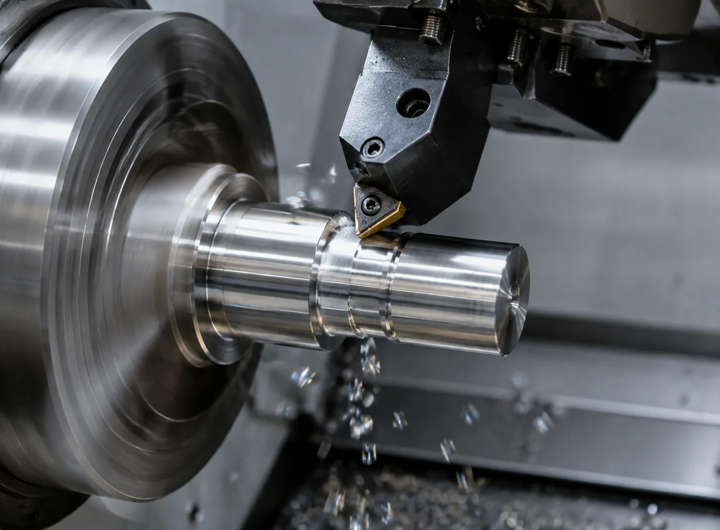
Why two programs can machine the same part at very different cost
Take a simple 6061-T6 aluminum bracket and give it to two programmers. The first one uses the default pocket strategy, a single end mill for roughing and finishing, and feeds and speeds straight from the tool manufacturer's catalog. The second one switches to a high-feed roughing strategy with a small radial stepover and a large axial depth, sizes a separate finishing tool, and tunes the feed against a measured chip load. Both parts come off the machine inside tolerance. The difference is that the first one took twice as long, loaded the spindle harder, and left a worse finish to clean up — and nobody on the floor could tell why from looking at the part.
The reason is that CAM software, by default, programs conservatively. It has to, because it does not know your machine, your workholding, or how far your toolholder sticks out. The default toolpath assumes a rigid setup and a generic tool, then leaves margin on top of that. All of the money in CAD-CAM optimization is in clawing that margin back deliberately — knowing, rather than guessing, how much engagement the tool and the part can actually take. The three levers that matter, in order of impact, are engagement control, roughing strategy, and feed-and-speed calibration. Tool selection and verification wrap around all three, because a brilliant toolpath programmed for the wrong tool is still a scrap part.
Engagement control is the dial that matters most
Tool engagement is the single largest driver of whether a cut runs fast, stays cool, and holds a tool. When a cutter runs at full width — the full diameter buried in the metal — the cutting edge is in contact with the workpiece for a long arc of every rotation. That means maximum cutting force, maximum heat going into the tool, and a chip that is thick at entry and thick at exit. When you reduce the radial engagement to a fraction of the diameter, two things happen at once: the force drops, and the chip thins. A chip that is thinner than the programmed feed per tooth cuts with far less load, which is the mechanism behind chip thinning — the effect that lets you raise the feed rate substantially and still remove material faster than the full-width cut, with a fraction of the force.
The practical version is that a 12 mm end mill taking a 20% radial stepover can often run at three to five times the catalog feed rate on the same spindle, because the thin chip keeps the load within the tool's limit. The same logic applies to the entry and exit of every contour. A toolpath that plunges straight into the part and then turns a sharp corner is slamming the tool through maximum engagement at exactly the moment it is also accelerating; a toolpath that arcs into the cut and rolls through the corner keeps the engagement angle nearly constant. Constant-engagement toolpaths are the core of modern CAM, and they are the first thing to check when a program is chattering, breaking tools, or running slow.
Roughing strategy: adaptive clearing versus traditional pocketing
The roughing pass is where most of the cycle time lives, so it is where the strategy choice pays back fastest. Traditional pocketing clears a pocket in full-width, back-and-forth passes at a fixed stepover. It is simple, predictable, and hard on tools in the corners, where the engagement jumps the moment the cutter wraps around an inside radius. Adaptive clearing — also called trochoidal or high-speed roughing — does the opposite: it holds a constant, light radial engagement and runs at a high feed with a large axial depth of cut, following a spiral or trochoidal path that never lets the tool bury itself in a corner.
Adaptive roughing wins on three counts. First, the constant light engagement lets you use the full flute length, so a deep pocket is cut in one pass instead of several shallow ones. Second, the light load is far easier on the tool, which matters most in tough or work-hardening materials like stainless and titanium, where a full-width cut is a guaranteed way to shorten tool life. Third, because the force is steady, the part sees less flex, and thin walls and small parts stay straighter. The trade-off is that adaptive toolpaths generate a lot of small repositioning moves, so they depend on the machine's acceleration and on a CAM system that links those moves into smooth arcs rather than stopping at each one. The table below is the working comparison, and the honest summary is that on anything deeper than a shallow open pocket, adaptive roughing is the better default.
| Strategy | Engagement | Axial depth | Feed rate | Tool load | Best for |
|---|---|---|---|---|---|
| Traditional pocketing | Full width, fixed stepover | Shallow | Catalog | High, spikes in corners | Shallow open pockets, soft material |
| Adaptive / trochoidal | Constant light radial | Full flute length | High (3–5×) | Low, steady | Deep pockets, tough alloys, thin walls |
| High-feed roughing | Light, large radius insert | Shallow | Very high | Low–moderate | Face and bulk stock removal |
| Plunge / peck roughing | Axial plunge | Deep | Moderate | Axial only | Deep cavities, weak spindles |
The pattern to read from the table is that the faster strategies all trade engagement for feed rate. They do not cut more aggressively; they cut more intelligently, spreading the same removal rate over a lighter, steadier load so the tool and the part survive it.
Tool selection inside the CAM environment
The toolpath is only as good as the tool the CAM system thinks it is driving, and a mismatch here is where most programs quietly go wrong. The CAM library stores a tool by its diameter, flute count, and material, but the two numbers that decide whether the program actually runs are not always front and center: the stickout, and the corner radius. A 10 mm end mill programmed at a 30 mm stickout is a different tool from the same mill at a 15 mm stickout — the longer one deflects far more under load, which shows up as chatter, taper, and oversize corners that no amount of feed tuning will fix. The rule is to program the tool as short as the part allows, and to model the real stickout in the CAM setup rather than the default.
Flute count is the second quiet decision. A two-flute end mill clears chips well in aluminum but leaves a rougher finish and less support than a four-flute tool at the same feed; a four-flute tool cuts smoother and can run faster in steel but packs chips in deep slots. For roughing aluminum, fewer flutes and more chip room; for finishing steel and for small diameters, more flutes for rigidity. Coating follows the material — an uncoated sharp edge for aluminum, a TiAlN or similar hard coating for steels and heat-resistant alloys. Getting these right inside the CAM library means the feed-and-speed numbers the system recommends are at least starting from a tool that matches the job, instead of a generic one.
Feed and speed: catalog numbers versus calibrated numbers
The feed and speed in a catalog are a starting point, not a promise. They assume a rigid machine, a short tool, an ideal holder, and a material that matches the exact grade on the datasheet — and real material rarely matches. Two bars of "6061" from different mills, or the same 316L stainless from different suppliers, will cut differently enough that the catalog numbers leave margin on the table or push the tool past its limit. The only way to know is to calibrate against the machine: start from the catalog number, then read the chips, the load, and the finish, and adjust.
What to look for is specific. In aluminum, a thick, well-formed chip that curls and breaks cleanly says the feed is right; a fine, powdery chip means the feed is too low and the tool is rubbing, which builds heat and kills the edge. A rising spindle load with a falling feed per tooth means the tool is dulling and the program should have a wear offset built in. Surface finish is the last read: chatter marks mean the engagement or the stickout is wrong, and a dull, smeared finish in aluminum means the tool is running too slow and smearing material instead of cutting it. Calibration is not a one-time step; it is the difference between a program that was looked up and a program that was dialed in.
Verification and post-processing: catch the crash before the machine does
The last piece of CAD-CAM optimization happens before any metal is cut, and it is the cheapest insurance in the whole process: simulation, collision checking, and a correct post-processor. A machine simulation that includes the real tool, holder, fixture, and stock lets you see a gouge, a collision, or an over-travel on the screen instead of on the spindle. The value is not just catching the catastrophic — the holder that would hit the clamp — it is catching the expensive, subtle stuff: a rest-machining pass that leaves a sliver of stock, a rapid move that crosses through the part, a corner that the roughing pass could not reach and the finishing pass will now slam into.
The post-processor is the part most shops under-invest in. CAM generates tool movement in the software's own coordinate logic; the post-processor translates that into the exact G-code dialect of the specific control on the specific machine. A wrong post-processor can turn a perfect toolpath into arcs the control interprets as linear moves, rapids at the wrong height, or a tool change the machine does not know how to read. The output is also the place to add the details that make the operator's life sane: a tool list with the real stickout, a setup sheet with the work offsets, and a program header with the part number and revision. A program that verifies clean and posts clean is the only kind that should ever reach the machine.
- Check engagement before feed. Reduce radial stepover to lighten the chip, then raise feed to recover the removal rate — never the reverse.
- Rough with adaptive clearing on deep pockets and tough alloys, and reserve full-width pocketing for shallow, open, soft-material features.
- Model the real stickout and toolholder in CAM. A long tool changes everything downstream; program it short and state it.
- Match the flute count and coating to the material, not to the default library entry.
- Calibrate feeds and speeds against the machine, reading chips, spindle load, and finish instead of trusting the catalog.
- Arc into cuts and roll through corners so engagement never spikes at entry or in an inside radius.
- Simulate with the real fixture and stock, and fix the gouge on the screen, not on the spindle.
- Verify the post-processor output on the control before the first run — a clean CAM session does not guarantee clean G-code.
"A machining program is a set of decisions you make once and pay for on every part. Get the engagement right, and the same machine, the same tool, and the same material suddenly run faster and last longer — not because anything got more powerful, but because the toolpath stopped fighting the metal and started cutting it. The CAM system is not the machinist; it is a very literal assistant that does exactly what it is told. The skill is in the telling."
CAD-CAM optimization is less about buying faster software and more about removing the margin that generic defaults leave on the table. Control the engagement, choose the roughing strategy by the geometry and the alloy, model the real tool, calibrate the feed against the machine, and verify before the first cut — and the same part comes off the same machine faster, with better finish and longer tool life. The levers are all in the planning; the machine just follows orders.
If you are quoting a part and want the toolpath planned — not just programmed — send the drawing over and we will walk you through the strategy before a single part ships, from CNC milling to the 5-axis setup that removes the most setups in one go.